[PP_CONVERTTOPOWERLINE]
Creates a power line (alignment and supports) from a line entity
When the command starts, select a linear element. The following prompt appears in the command line:
Select LINE, POLYLINE or 3D POLYLINE to convert:
The linear element can be either drawn in the drawing or imported as geospatial data (GIS data), e.g. ESRI Shapefile (.shp), KML/KMZ (.kml and .kmz), ESRI Geodatabase (more complex GIS datasets stored in an Esri geodatabase structure) or data from the GML (Geography Markup Language) file format.
After the element is selected, the power line alignment direction is shown graphically with arrows and the following prompt appears:
Arrows show trace direction. Click to toggle, ENTER to confirm:
Left-click to change the start direction of the trace. Press ENTER or right-click to confirm the direction and open the dialog.
If the selected entity is not supported, the following message appears in the command line:
Must be a LINE, POLYLINE or 3D POLYLINE. Try again.
Options:
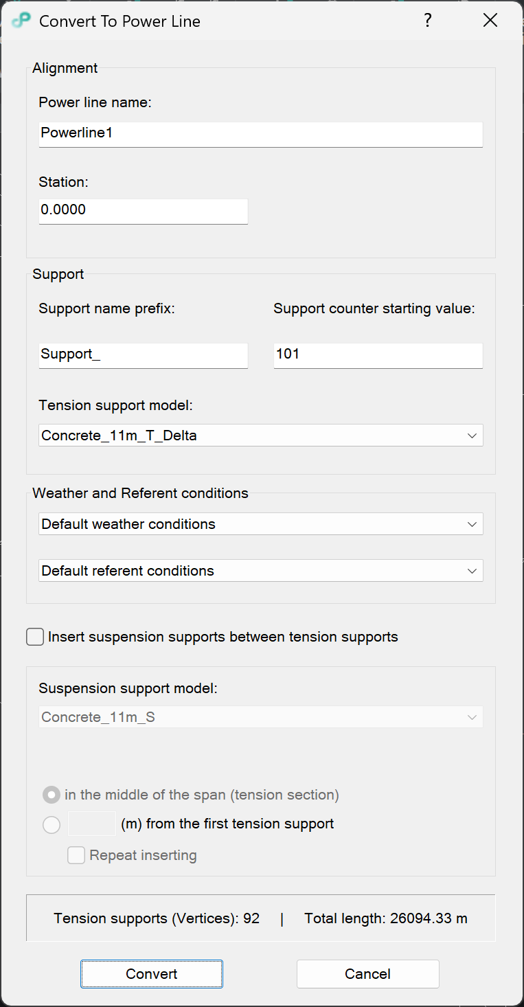
- Power line name: unique name of the power line.
- Station: first support station.
Note: the number should be entered as 1234.5 (1+234.5 not supported)
- Support name prefix: a string which each support name starts with. It can be empty.
- Support counter starting value: number of the first support, if it is left empty 0 is assumed.
- Tension support model: support data model which will be used for tension supports. A tension support is created at each vertex of the selected entity. The value is, also, set as default one for initial value in Add Support dialog.
- Weather and referent conditions: models used for power line calculations. By default, chosen models will be used when adding conductors or ground wires.
- Insert suspension supports between tension supports checkbox: if checked, suspension supports are inserted between tension supports and the options below are enabled.
- Suspension support model: support data model which will be used for suspension supports. The value is, also, set as default one for initial value in Add Support dialog.
- In the middle of the span (tension section): inserts a suspension support in the middle of the span between two tension supports.
- (m) from the first tension support: inserts a suspension support at the entered distance, in meters, from the first tension support of the span.
- Repeat inserting checkbox: if checked, suspension supports are inserted repeatedly at the entered distance.
- Tension supports (Vertices) and Total length: information about the selected entity: the number of tension supports (vertices) and the total length of the power line.
- Convert button: creates the power line (alignment and supports) from the selected entity.
- Cancel button: cancels the command.