What is new in the software solution Power Path V23 version?
The POWER PATH team is constantly developing and improving the Power Path © solution, behind the scenes; every day, our development and support team is creating, improving, and researching new functionalities to provide customers with new approaches to power line design. In front of you is What is new document which describes what the latest version brings.

The latest version of the Power Path solution is Power Path V23, build 23.2.07.

Enjoy exploring and using the new functionalities!
Foreword
Power Path provides numerous benefits in power line design:
- reduction of information-sharing restrictions,
- project transparency increase,
- project visualization improvement,
- 2D design and advanced 3D BIM modeling,
- calculation reports generation,
- power line elements customization,
- IFC (BIM) models export/import,
- SHP (GIS) data import/export,
- Online maps import.
Power Path solution is not limited just to the power line design process, it is a powerful CAD and BIM solution for 2D drafting and 3D modeling in the AEC (Architecture, Engineering and Construction) industry and supporting GIS data.
Added new commands
Geospatial data
In order to support a more flexible and detailed design of the power lines we added new tools for geospatial data. Now workflow in V23 will be enriched and supported with possibilities for using online maps, point clouds, raster images, .shp (GIS) files and importing and editing point data.

Under the new ribbon panel group Geospatial data are added commands:
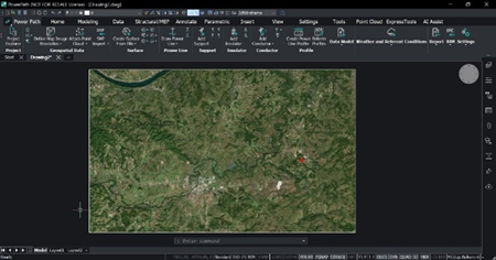
Online Maps
You can add and edit online maps from Bing Maps © service. Available commands:
- Load Online Maps
Description: Loads online hybrid, aerial and/or road map. You need to choose which map you want to load.


- Turn Off Online Map
Description: Turns off online maps. When your map is loaded, you can turn off the visibility of the map.

- Capture Map Image
Description: Captures geographic map image. Very often you don’t need to have a whole map (big area), you can just select which part of the area you want to load.


- Define Map Image Resolution
Description: Defines the resolution of the map image. Your loaded map can be with high and lower resolution and you can change it, it is dependent on which location of the map you load.

- Set Geographic Location
Description: Sets geographic location. If you import or load data that are not georeferenced it is necessary to define geographic location before you do that.

Point clouds
You can add and edit point cloud files from different file formats. Available commands:
- Attach Point Cloud
Description: Attaches point cloud to the drawing. Supported file formats for attaching: .e57, .las, .laz, .pts, .ptx, .rcp, .rcs, .hspc (.hspc is Hexagon Smart Point Cloud format).

- Point Cloud Manager
Description: Opens point cloud manager. In your project, you might have more than one attached point cloud data, with this command you manage point cloud data (preprocessing, inserting, deleting).

- Export Point Cloud
Description: Exports a point cloud. If you want to export point cloud data, you can export it in .pts, .laz, or .hspc file format.
- Color Map Point Cloud
Description: Assigns a color to a point cloud based on a range of variables. For better visibility of the point cloud elevation or intensities, you can assign colors to the attached point cloud.


- Align Point Cloud
Description: Rotates point cloud to align it with X and Y axes. If your attached point cloud data requires aligning in the space, you can do it with this command.


- Crop Point Cloud
Description: Crops a point cloud. If you want to crop some area of the point cloud data, you can do that with this command.


- Remove Point Cloud Crop
Description: Removes point cloud crop. If you want to remove an already cropped area, it is possible with this command.
GIS data
You can add and edit GIS files recorded in shape (.shp) file formats. Available commands:
- SHP Import
Description: Imports SHP data. Geospatial vector data .shp, which is a format developed by Esri ©, can be imported with all associated GIS data.


- SHP Export
Description: Exports SHP data. If you want to export .shp files it is possible with this command. The already imported .shp entities in the drawing will be exported with original or modified (if you modify) GIS data, CAD entities like polylines, lines, etc. will be exported without associated GIS data into a .shp file.


Raster Images
You can add and edit raster image files from different file formats. Available commands:
- Attach Raster Image
Description: Attaches a raster image to the drawing. Supported file formats for attaching: .bmp, .jpg, .jpeg, .pcx, .png, .gif, .tga, .tif, .tiff, .jp2, .j2k, .ecw, .sid, .mti.


- Clip Image
Description: Clips raster images. If you want to crop some part of the image, you can do that with this command.


- Set Image Quality
Description: Toggles image quality high/draft. This command allows you to set: the high or draft quality of the image.


- Turn Off Image Frame
Description: Turns off the image frame. When you attach an image, the image's frame will be visible by default, but with this command, you can turn off visibility.

- Turn On Image Frame
Description: Turns on the image frame. If you want to have a visible frame of the image, use this command to turn on visibility.

- Export Image
Description: Exports a raster image to a file. Raster images from a drawing can be exported to an external image file.

Civil points
You can add point data from different file formats. Available command:
- Civil Points Import
Description: Creates civil points. If you want to import survey points, you can define file formats for importing. It means the user can use native (predefined) file formats of the point or define your own format.


Surface
V23 is enriched with new commands for creating surfaces (from the point cloud and civil points), editing and modifying surfaces, labeling surfaces and creating and editing grading.

Under the ribbon panel group Surface are added commands:
Creating surface
You can create a surface from the point cloud and civil points. Added commands:
- Create Surface From Civil Points
Description: Creates TIN surface from Civil Points. After importing civil points, you can create a TIN surface by running this command and selecting points.


- Create Surface From Point Cloud
Description: Creates TIN surface from the point cloud. After attaching point clouds, you can create a TIN surface by running this command and selecting points.


Projecting on the surface
The previous version already supported assigning images but now you can also project other entities. Added command:
-Project to Surface
Description: Projects entities to TIN surface. Any of the entities like points, blocks, text, lines, polylines, and circles can be projected on top of the surface.


Editing surface
Surface editing is now improved with new commands. Added commands:
- Modify Surface
Description: Deforms or smooths a TIN surface. If you want to deform or smooth the surface with a predefined contour or shape, you can do that with this command.
- Merge Surfaces
Description: Merges two or more TIN surfaces into a single TIN surface. Sometimes you have different data inputs for creating surfaces and you need to use different options for creating. With this command, you can merge more surfaces into one TIN surface.

- Extract from Surface
Description: Extracts meshes, solids, points, faces, contours or borders from a TIN surface. If you want to generate some other CAD entity from a surface it is possible with this command.
- Surface Volume
Description: Creates a TIN volume surface between a base and a comparison TIN surface, or an elevation. If you want to calculate cut and/or fill between surfaces you can do that with this command.
Labeling surface
For a better preview and easier design of the power lines, there are commands for labeling a surface. Added commands:
- Add Surface Labels
Description: Adds label on the TIN surface. For the presentation of the elevation of the surface, there are a few options for labeling: major and minor contour labels, spot elevation labels and slope labels.

- Show Water Drop
Description: Creates a water drop path on the TIN surface. This command shows you how water flows from higher to lower points of the surface.

Grading
For creating a graded surface, there are commands for grading. Added commands:
- Create Grading
Description: Creates a graded surface on a TIN surface. For creating grading, you need to define a base entity (contour) and then offset or slop to project on the surface.

- Edit Grading
Description: Edits a graded surface. If you want to split, merge, or switch the grading direction you can use this command.


- Balance Grading Volumes
Description: Balance cut and fill volumes within the specified tolerance. If you need to balance volumes, it is possible with this command.


Blog
User informing and knowledge sharing is now enriched through the Power Path blog posts. Added command:
- Blog
Description: Opens a link to the Power Path Blog webpage. Visiting Blog you are up to date with the latest news about the solution and trends in power line design.

Upgraded or/and extended existing commands and functionalities for power line design
- Create Power Line Profile
Added new command for inserting safety distance from terrain in power line profile.


Added labels for tension value of each conductor/phase in power line profile. Default set unit is MPa, but it can be changed in [PP_SETTINGS].


Added new rubric in profile view - Rubric Power line direction change has been added in power line profile for labeling direction changes of each support.


Added new rubric in profile view - Rubric Supports number in the tension section has been added in power line profile for labeling support number.


Extended scale (ruler) in profile view – The scale is extended from 1 m to 15 m above the highest point of the terrain.

- Create Sag-Tension Report
Extended temperature range from -20 to -40 C degree for creating Sag Tension calculation.

- Create Support Report and Create Quantity Report
Improvements for power line direction change and support orientation angle in the support and the quantity reports. Converting is correct in different units [unit can be in degrees, radians, gradians and degrees/minutes/seconds]
- Create Sag-Tension Report, Create Support Report, Create Quantity Report and Create Powerline Coordinates Report
New command for creating reports in different languages. Reports can be created in Czech, German, Greek, English, Spanish, Estonian, French, Croatian, Hungarian, Italian, Lithuanian, Latvian, Norwegian, Polish, Portuguese, Russian, Slovenian, Serbian, Swedish, Turkish, Hindi, Romanian and Slovak languages.


Upgraded or/and extended other existing commands and functionalities
- BIM BCF Panel*
The login process has been enhanced, you don't have to manually provide the URL address of the BCF cloud service. The user creates a screenshot of the viewpoint with comments on the issue.
An issue is being recorded in .bcf file and synced to the BCF cloud service (you can use some of the services such as BIM Track, BIMcollab, BIMsync).
Importing .bcf files from the local machine is also available.

- IFC Import*
The command is improved with the possibility of importing .ifczip file too. Also, improvements to IFC4 Import have been made, including support for IfcSectionedSolidHorizontal, IfcAlignmentCurve, IfcLinearPlacement, and better handling of split objects (walls) to be more consistent with the latest buildingSMART requirements.

* Command is available in Power Path BIM package.
Fixed existing commands and functionalities
- Create Sag-Tension Report
Fixed Sag Tension report for part Load calculation at -5 C degree (names of sag and tension were incorrectly defined in the table).

- IFC Export
Fixed units for orientation and temperature in IFC record (.ifc file).

Improved user interface
Power Path’s user interface has improved for a better user experience. If you want to customize the workspace, run the command CUSTOMIZE.

Try Power Path V23
If you want to start creating your power line projects using the BIM approach, import your data and use the solution for any of your 2D drafting and 3D modelling in engineering projects, try Power Path solution.
To download and try Power Path V23, visit the product website https://www.power-path.com/ and submit a request.
Thank you for choosing Power Path - we hope you enjoy using it and that it makes your design process easier!
Software developer:
POWER PATH DOO
email: contact@power-path.com
web page: https://www.power-path.com/
(Date of the document January 2024.)